Link Budget of Receiver

Tools for Estimating Range of RF Communication

Marcel Merchat
RF and Microwave Engineer

RF Link Budget

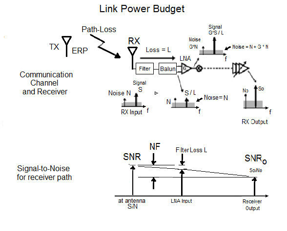
The key concepts of formulating a power link budget include these factors:

  • Friis Transmission Formula for signal loss over RF Channel Distance
  • Power Spectrum Density
  • Thermal Noise
  • Signal-to-Noise Ratio
  • Quantization Noise
  • Bit Error Rate
  • Shannon's Theorem for Channel Capacity
  • Receiver Sensitivity

Communication Link and Budget


ERP: Effective Radiated Power

ERP: Effective Radiated Power

Path-Loss: Loss in RF Channel

SNR: Signal-to-Noise (S/N) at Antenna

N: Noise Floor at Antenna

NF: Receiver noise figure

SNRo: S/N at receiver output

The signal-to-noise ratio of the radiated signal is very high when there is no external interference. The signal to noise ratio at the receiver input is much lower because of thermal noise generated inside the receiver.

Maximum Transmitter Power

In some cases, government regulations limit transmit power directly and in other cases there is a limit for power spectral density. As an example, consider the WLAN 802.11a limit of 2.5-mW per MHz over a 16-Mhz bandwidth. The maximum effective transitted power is 40 mW or 16 dBm.

BW <- 16                ## Bandwidth is 16 MHz
PSD <- 0.0025           ## PSD is 2.5 mW/MHz
ERP <- 1000 * BW * PSD  ## Total power for 16-MHz band
## [1] "The maximum effective radiated power for the transmitter is  40 mW."
## [1] "This is equivalent to  16.0 dBm."

RF Path Loss

To cover 300 feet at 5-GHz requires a path loss of 86 dB. We describe this important antenna problem separately in another slide show. This results in a receiver signal of -70 dBM. The 802.11a specification requires that the signal must not exceed -65 dBm at 300 feet.

pathlossdB <- 86
receiver_signal <- ERPdB - pathlossdB ## Signal at 300 feet
receiver_signalstring <- formatC(receiver_signal , format = "f", digits = 1)
## [1] "The signal at the receiver is  -70.0 dBm."


I built a dashboard for path loss at this web site.

Thermal Noise Floor

The noise floor at the receiver input is -174 dBm/Hz over the 16 MHz bandwidth. This generated noise power of -102 dBm at the input ot the receiver.

thermaln <- -174         ## PSD/Hz of thermal noise in dBm units 
p <- 10^(thermaln/10)    ## convert to real number
pbw <- p * 16 * 10^6     ## Multiply by 16 MHz
floor <- 10 * log10(pbw) ## Convert to dBm
num <- formatC(floor, format = "f", digits = 1)
## [1] "The noise level at the antenna is  -102.0 dBm."

The bit error rate (BER) is used to calculate the minimum signal-to-noise ratio (SNR) at the output of the receiver. The minimum SNR limits the size of the receiver noise figure.

Required Bit Error Rate for Receiver

For 64 QAM, the required signal-to-noise is 27 dB at 54 MHz. This is an interesting problem in itself and will be covered by a separate slides. Since the packet length for 802.11a is 8-kB and assume error-correction-coding can handle 10% data loss, our BER requirement is approximately \(10^{-5}\) as follows:

\[(1-BER)^{8000}=1-0.1\].
BER <- 1 -  10^(log10(0.9)/8000)
## [1] "The required bit error rate (BER) is  0.000013"

Required Noise Figure for Receiver


NFR = [TX Power] - [Path Loss] - [Required SNR] - [Noise Floor]

NFR = 16 dBm - 86 dBm - 27 dBm - (-102 dBm) = 5 dBm


The noise figure of the receiver (NFR) must be 5 dB or lower.

## [1] "The required signal-to-noise ration for the receiver is  4.98 dB"

Noise Figure

The noise figure of a circuit block is defined as follows:

\[NF = \frac {SNR_{in}} {SNR_{out}}\]

Here is the same formula in decibel units:

\[NF (dB) = SNR_{in} (dB) - SNR_{out} (dB)\]


Marcel Merchat


August 2, 2017